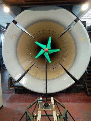
3D-printed horizontal-axis micro wind turbine
Objectives
Objectives of this project were deduced from two facts. The first one is that the renewable energies are more and more important in our society. They are one of the solutions we found at actual energetical and ecologial problems we have to deal with. The second one is that more and more Fab labs are created. These places allow everyone to realise self-designed objects. 3D printers are some machines among others that can be used to create these objets.
Based on these two facts, we defined the subject of our project: the design and test of a 3D-printed horizontal axis windturbine.
Design
In this part, we will explain the main design choices that we made
3D printer
The printer that we used is a Up Mini. We chose this printer because it has a good precision of printing and uses a thermoplastic, the ABS. The ABS possesses better mechanical properties than the others thermoplastics available on the other printers. The ABS is more ductile and more resistant. The main constraint we will have to deal with with this printer is the maximum size of the pieces to print. Indeed, the printing volume of the Up Mini is of 120 x 120 x 120 mm.
Generator
The generator that we chose is a Maxon EC-40. This generator is followed by a gearhead that allowed to increase the permitted maximum admission torque to 1.48Nm. It also enables some admission rotational speeds that are consistent with those of the hub untill 758.4rpm. An encoder connected to the generator allows to know at every moment its rotational speed.
Blades
Due to the printer choice, we were forced to create blades in several pieces. We decided to design two sets of blades. The first one has a 70cm diameter and blades are formed of 3 pieces. The second one possesses a 100cm diameter and blades are made of 4 pieces (see picture of assembly). To determine the shape of these blades, we used a matlab program that gives the form and the twist of the profiles as function of the radius. This matlab program takes as arguments: the type of profile used, the design wind speed, the design tip speed ratio and the desired rotor radius (for more details: see master's thesis). The implemented method is a improved version of the Blade Element Momentum method (BEM)
Hub
The hub has two main functions: to assure the blades position avoiding any rotation or unhooking of those, to transmit the torque to the generator. In our project, the different blades foots placed together form a cylinder. This one is then covered by the two parts of the hub. We maintain the assembly fixed with nuts and bolts. The first part, the nose, possesses also an aerodynamic function. The second part is resistant and fully printed because it transmits the torque to the generator. The assembly between the hub and the generator uses a key. A compression screw was added to press the key and maintain the rotor in place on the generator shaft.
Nacelle
The main function of the nacelle is to maintain the generator in position and to maintain all the assembly stable on the top of the tower. The tail fin is also fixed on the nacelle. It will orientate the hub en front of the wind. We decided to use the 3D printing to create an original shape. Indeed, 3D printing allows the design of pieces that would be extremely expensive to create with classic manufacturing means. The shape we designed uses the Venturi effect to create an air flux on the surface or the generator. It permits to cool it more efficiently and so to increase the general efficiency. The ABS is a thermoplastic and doesn't resist at high temperatures. In our project, the uses of this type of cooling turned out to be necessary. The assembly of the nacelle is shown on the hereby picture.
Manufacturing & Assembly
The different pieces we designed during the project are available in CAD format and stl format. The first format allows anybody who would like to do it to improve the pieces or to try new designs. The second one is the format used by most 3D printers. It allows the direct printing of the prototype.
The main parameters that we used for the manufacturing of the pieces are the printing precision and the filling. Regarding precision, we used the best precision available on the Up Mini, layers of 0.2mm. The precision is important for the profiles of the blades because it influences the aerodynamics. The Up Mini has 4 different filling parameters: negligible, slight, medium and full. We used te medium filling for most of the pieces. It allowed to obtain pieces sufficiently resistant for reasonable masses and costs. Moreover, it was important not to weigh down the blades to limit centrifugal stresses. The only pieces fully filled are:
- the hub part that transmits the torque because it is the piece more inclined to delamination
- the parts of the nacelle that constrain the generator because they also suffer important stresses
The assembly of the different parts is simple:
- blades are assembled with threaded rods and M3 nuts. Keys used to guide the assembly have a parallelipiped shape with a 4mm side. (see technical drawings for all lengths (it depends on the set of blades choosen)).
- All others bolts and nuts used in our design are M5 (lengths are available on technical drawings)
